
According to PS Market Research, the global CNC machining market hit $74.9 billion in 2024. That number is on track to reach $160 billion by 2032. Choosing the wrong hole type can cause part rejection, assembly failure, or costly rework.
This guide covers 7 standard CNC hole types, which materials drill cleanly, and the design rules that keep parts accurate and cost-efficient.
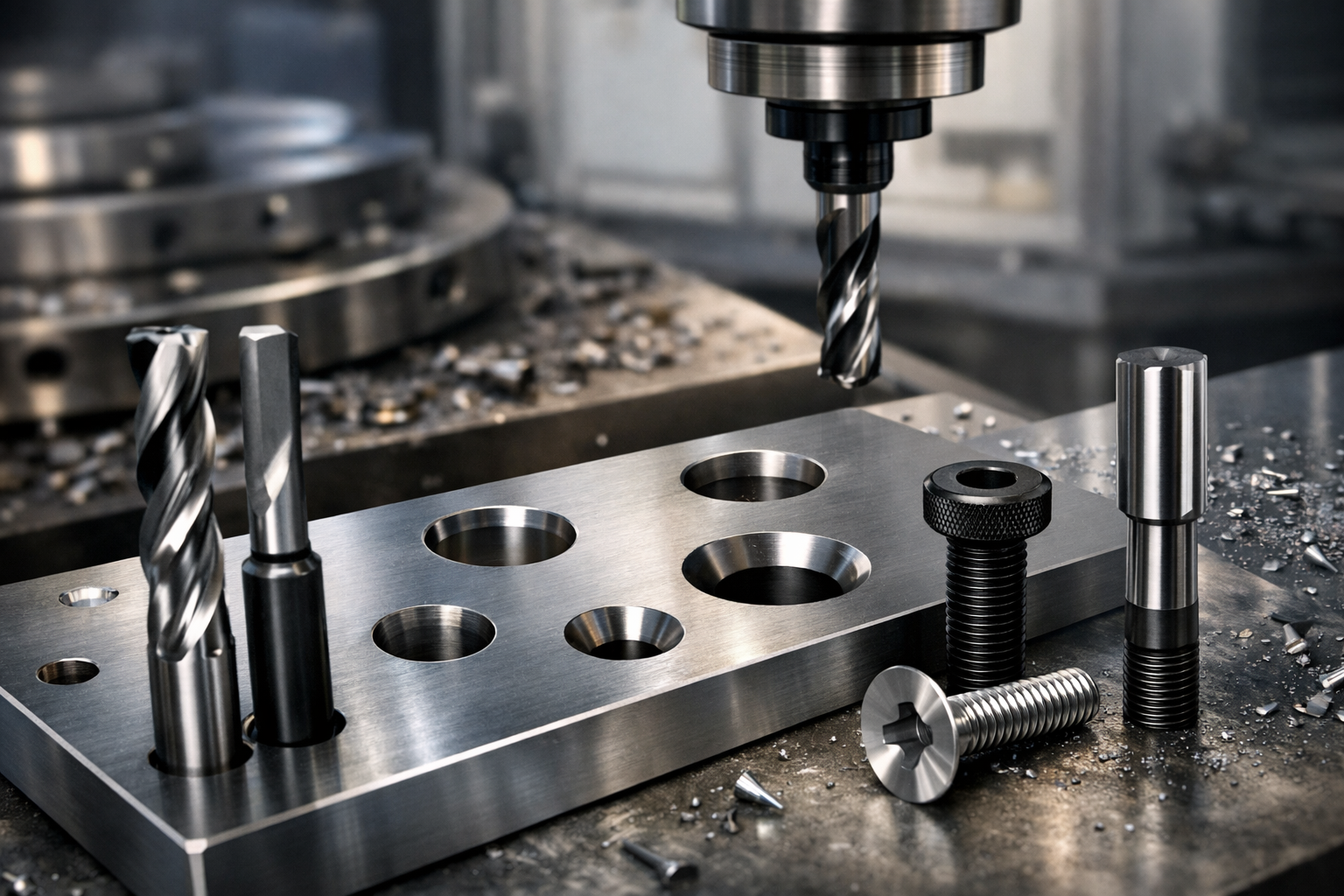
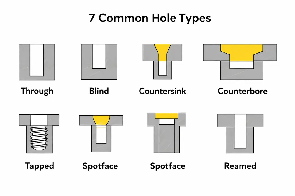
7 Common Types of Holes in CNC Machining
The 7 types below each serve a distinct function with specific tolerance requirements.
Through Hole
A through hole passes completely through the workpiece, making chip evacuation easy and tool deflection minimal. Through holes are standard for bolts, dowel pins, and any fastener that needs a nut on the opposite side.
Blind Hole
A blind hole stops at a set depth without breaking through the opposite face. The bottom is naturally conical at roughly 118°; a flat bottom requires an extra end mill pass and adds cost. Depth control matters: too shallow and the fastener bottoms out; too deep and you risk breaking through.
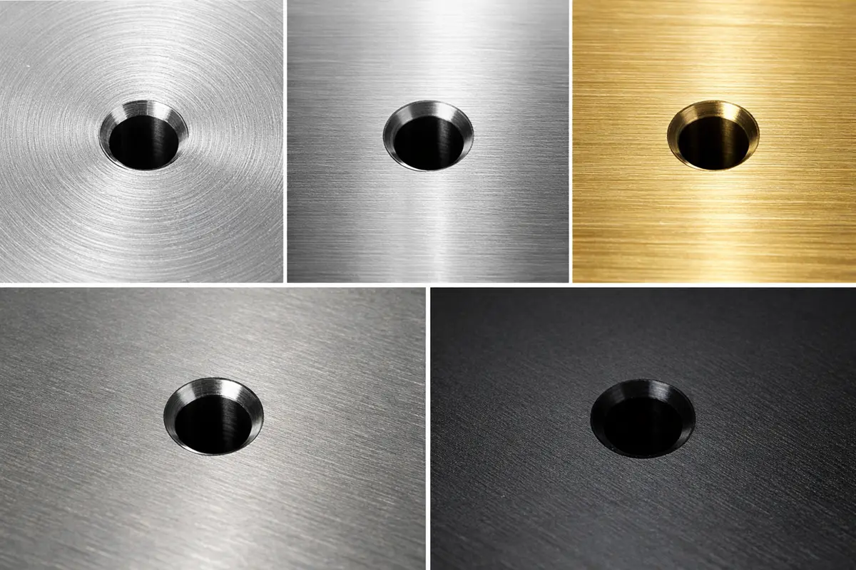
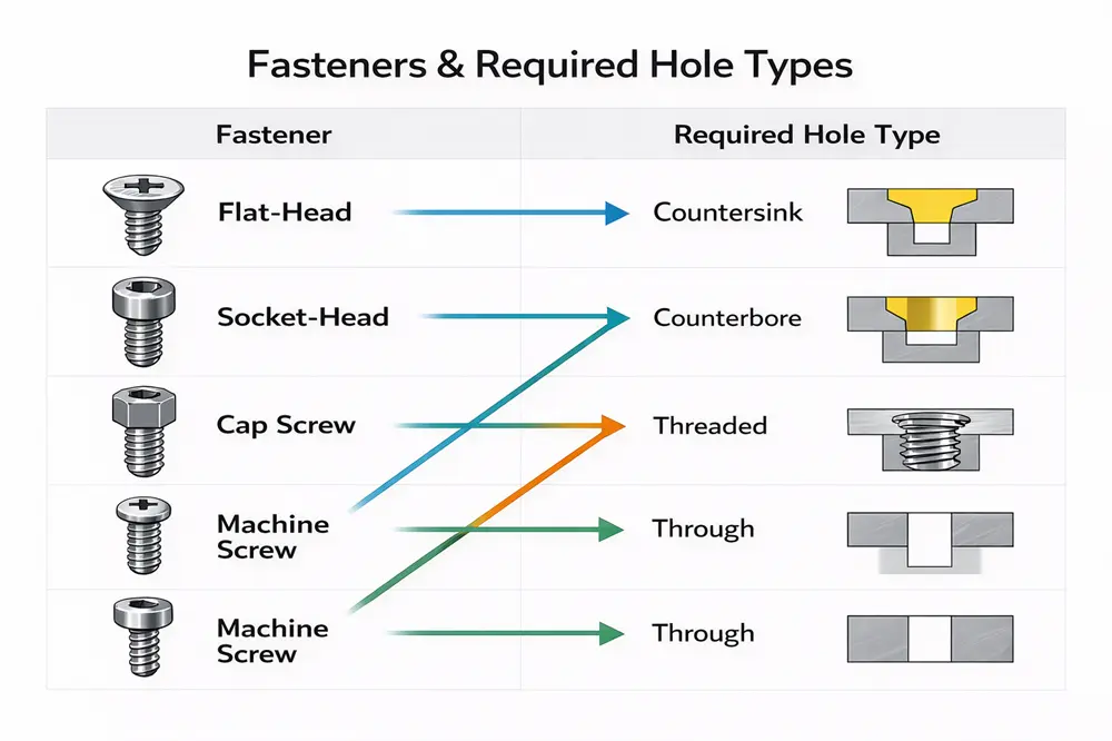
Countersink Hole
A countersink hole is a conical taper cut at the hole entrance, typically at 82° or 90°. The tapered recess lets a flat-head screw sit flush with the part surface. Without one, the fastener head sits proud and blocks mating surfaces.
Counterbore Hole
A counterbore hole is a flat-bottomed, cylindrical recess at the hole entrance. The recess diameter matches the screw head; the depth matches the head height, pulling a socket head cap screw (SHCS) fully below the surface.
Tapped Hole
A tapped hole is a hole with internal threads cut by a tap. The thread geometry lets a bolt engage directly with no nut needed. Under-tapped holes strip easily; over-tapped holes in thin sections can crack the wall.
Spotface Hole
A spotface hole is a shallow, flat-bottomed recess, typically 0.5–1.5 mm deep, machined on a curved surface to create a perpendicular seat for a fastener head or washer. Without one, the fastener rocks under load, causing uneven clamping force and fatigue cracking.
Reamed Hole
A reamed hole is drilled undersized first, then finished with a reamer to hit H7 tolerances (±0.01 mm). Standard drilled holes carry ±0.05–0.1 mm variation, too loose for locating pins or press-fit bearings.
Hitting H7 consistently requires both the right tooling and in-process verification. Shops like Rollyu Precision use plug gauges after every reaming operation to confirm the tolerance before the part moves to the next stage.
Different Types of Holes Comparison Table
The table below maps each hole type to its geometry, tolerance, and primary use for quick reference.
|
Hole Type |
Bottom Shape | Typical Tolerance | Primary Use |
| Through Hole | Open (exits part) | ±0.05–0.1 mm |
Bolts, dowel pins, clearance fits |
|
Blind Hole |
Conical or flat | ±0.05–0.1 mm | Threaded inserts, hidden fasteners |
| Countersink | Conical taper (82°/90°) | ±0.1 mm |
Flush flat-head screws |
|
Counterbore |
Flat-bottomed cylinder | ±0.05 mm | Recessed socket head cap screws |
| Tapped Hole | Flat or conical | Per thread class (ISO 965 / ASME B1.1) |
Direct bolt engagement, no nut |
|
Spotface |
Flat (shallow) | ±0.05 mm | Flat bearing seat on curved surfaces |
| Reamed Hole | Open or blind | H7 per ISO 286-1 (varies by diameter) |
Press fits, locating pins, bearings |
This table maps seven standard CNC hole types by bottom geometry and tolerance. Each profile is paired with its primary fastener application.
What Materials Are Suitable for Drilling Holes?
Picking the wrong tooling or feed rate causes oversized holes, torn edges, or broken taps. Both come down to two factors: material hardness and chip behavior.
Aluminum, Brass, Copper
Soft metals are well-suited for hole machining and work with standard tooling across all common hole types.
- Aluminum (6061, 7075): Drills fast with HSS or carbide tooling. Chip evacuation is clean and tolerances hold well, making it the lowest-effort material in this group.
- Brass (C360): Cuts cleanly with minimal burring. That’s why it’s the go-to for precision threaded parts and valve fittings where surface quality at the hole wall matters.
- Copper (C110): Soft, but gummy. Material tends to build up on the cutting edge, pushing hole diameter over spec if feed rate isn’t kept consistent.
Steel, Stainless Steel, Titanium
Hard metals are suitable for all hole types but require the right tooling and cutting parameters to avoid work hardening and heat damage.
- Steel (1018, 1045): Drills predictably under normal conditions. The main risk is heat buildup in blind holes, where chips have nowhere to go and coolant flow needs to stay consistent.
- Stainless steel (304, 316): Work-hardens fast. Any dwelling or feed slowdown causes the edge to rub rather than cut, leaving a hardened layer that tightens the hole and dulls the drill.
- Titanium (Grade 2, Grade 5): Low thermal conductivity means heat stays at the tip instead of leaving with the chip. Tool wear accelerates quickly without high-pressure coolant and conservative parameters, a critical rule for Space and Satellite components.
Delrin, Nylon, Acrylic
Engineering plastics support most standard hole types but require tighter process control around heat and moisture to hold final dimensions.
- Delrin (acetal): The easiest plastic to drill. Low friction, high stiffness, and clean chip flow put it close to aluminum in terms of process simplicity.
- Nylon (PA): Absorbs moisture after machining. Holes drilled to nominal size can end up undersized once the material swells in a humid environment.
- Acrylic (PMMA): Brittle under lateral pressure. It cracks before it deflects, so slow feed rates and sharp tooling aren’t optional. They’re required. No solvent-based coolant either.
Composites and Exotic Materials
These materials demand specialist tooling or non-conventional methods. Standard setups will either wear out fast or produce unusable holes.
- Carbon fiber (CFRP) and G10/FR4 fiberglass: Highly abrasive, wearing standard tooling within a single run. Both delaminate at the hole exit if feed rate isn’t backed off before breakthrough.
- Inconel and nickel alloys: Work-harden faster than stainless and trap heat at the cutting zone, leaving no margin for parameter errors.
- Ceramics (Alumina, Zirconia): Conventional drilling isn’t viable. EDM or diamond grinding are the only practical options.
How to Choose the Right Hole Type for Your Project
Choosing the wrong hole type means the fastener won’t fit, the assembly won’t hold load, or the part comes back for rework. These four factors narrow it down before machining starts.
Determine the Functional Purpose
Start with what the hole needs to do. Passing a bolt through two plates means a through hole. Anchoring into a single part with no back access means a blind hole. If the joint needs to resist lateral shift, a reamed hole with H7 tolerance is the right call.
Consider Fastener Types and Head Styles
The fastener head drives the recess geometry. Flat-head screws need a countersink. Socket head cap screws need a counterbore. Standard hex bolts need nothing beyond a clearance through hole. If the fastener threads directly into the part, the hole needs to be tapped to the correct standard (UNC, UNF, or metric M-series).
Assess Material Thickness and Strength
Material thickness sets a hard limit on hole type. Blind holes need wall stock below the depth of at least 20–25% of the hole diameter to avoid breakthrough. For tapped holes, keep thread engagement at 1.5× the screw diameter for steel and 2× for aluminum to avoid stripping.
Evaluate Cost and Machining Time
Through holes are the cheapest. Every added feature, whether a countersink, counterbore, tapping cycle, or reaming pass, raises both machining time and scrap risk. If tight tolerances or flush fasteners aren’t functionally required, a simpler hole type keeps cost down.
5 Essential Design Tips for Machined Holes
Poor hole design raises scrap rate, drives up cost, and forces redesigns.
Stick to Standard Hole Sizes
Non-standard hole sizes require custom tooling, adding lead time and cost with no functional benefit in most cases. Standard metric drill sizes run from Ø1 mm upward in increments of 0.5–1 mm; inch sizes follow 1/64″ steps.
Keep Hole Depths Manageable
Holes deeper than 4× the hole diameter create chip evacuation problems and tool deflection. Pushing past this limit requires specialized deep hole drilling techniques. Conversely, blind tapped holes shallower than 1.5× thread diameter don’t leave enough engagement for a reliable joint.
Design Flat Entry and Exit Surfaces
A drill entering at an angle deflects sideways on contact, pulling the hole off-center. On through holes, a flat exit surface keeps the drill from deflecting as it breaks through, maintaining consistent diameter.
Avoid Intersecting and Partial Holes
When two holes intersect or overlap at part edges, the cutting tool loses support mid-cut, producing an oversized, out-of-round hole and leaving sharp edges that damage mating parts during assembly.
If intersecting holes are unavoidable, drill the larger hole first. The smaller drill has more wall support.
Maintain Adequate Wall Thickness
Walls thinner than 1.5 mm around a hole deform under cutting forces and clamp pressure. A minimum wall thickness of 1.5× the hole diameter works for most metals; plastics typically need 2×. Spacing two adjacent holes less than 1× the hole diameter apart leaves too little material between them, causing deformation during machining.
FAQ
What Is the Difference Between a Counterbore and a Spotface?
A counterbore pulls a fastener head fully below the surface. A spotface only flattens an uneven surface to create a clean bearing seat, typically 0.5–1.5 mm deep.
Why Are Standard Drilled Holes Slightly Larger Than the Drill Bit?
Drill bit deflection and heat expansion during cutting both push the hole diameter above nominal, typically by 0.05–0.1 mm. Reaming corrects this for tight fits. For larger precision enlargements, compare boring vs drilling.
What’s the Minimum Wall Thickness Around a Machined Hole?
For most metals, 1.5× the hole diameter. Plastics need at least 2× because they flex under tool pressure.
Conclusion
Getting the hole type wrong costs more to fix than to get right the first time. Match the hole to the fastener head, respect material and depth limits, and stick to standard sizes. If your design needs a second set of eyes, Rollyu Precision offers free DFM review with every quote for custom CNC machining parts to catch hole design issues before they become scrap.