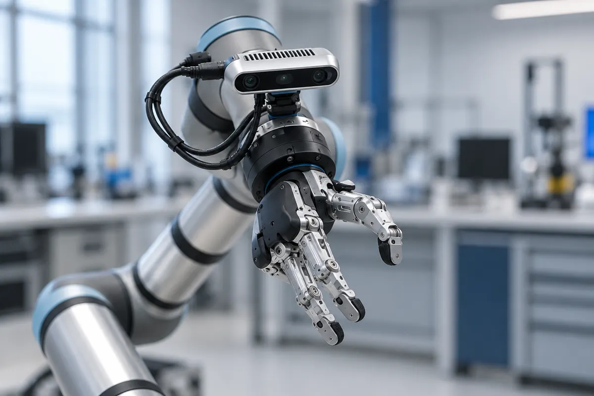
Choose gripper fingers that fit the gripper, hold the workpiece securely, and clear the next operation. Match the finger body’s material to the load and reach, pick a contact surface for grip and part protection, and check the design against the gripper manufacturer’s finger-length, mass, and moment limits before machining.
What Are Gripper Fingers?
Gripper fingers are the attachments on a mechanical gripper’s moving jaws that touch the workpiece during pickup, transfer, and placement, and custom fingers adapt that contact to a particular part or task. The actuator supplies motion and force, while the fingers position the contact surfaces and carry the load back to the jaws. Their length, offset, and profile set both the loads at the gripper jaws and the clearance around the workpiece.
Which Materials Work for Gripper Fingers?
Treat the finger body and the contact surface as two material decisions. The body has to carry load without excess mass or deflection, while the contact surface has to grip and protect the part, so a machined metal body with a replaceable polymer or elastomer insert often handles both jobs.
| Material or Contact Option | Reason to Consider It | Design Limit to Check |
|---|---|---|
| Aluminum | Lightweight bodies with machined mounting and contact features | Section stiffness, contact wear, and gripper mass limits |
| Alloy or tool steel | Fingers or inserts where stiffness or wear resistance drives selection | Added mass, grade, and heat-treatment condition |
| Stainless steel | Bodies or inserts exposed to corrosive operating conditions | Grade suitability for the environment and added finger mass |
| POM/acetal | Machined contours or inserts needing low moisture absorption and good machinability | Low friction in applications that depend on frictional holding |
| Rubber or other elastomer pads | Added compliance and grip at the contact surface | Compression, wear, and performance against the actual workpiece |
POM, also called acetal, machines well and absorbs little moisture, but its low friction works against fingers that hold the part by friction. Rubber pads or a suitable texture can add grip, as long as the contact surface still protects the workpiece finish. Test the chosen material pair under the actual contact conditions.
How Should Custom Gripper Jaws Be Designed?
Start with where the fingers grip the part and how they let it go. Reach and mounting geometry then connect those contact points to the gripper.
Contact Geometry and Part Release
Contoured fingers locate the part and restrain it by shape, while flat opposing faces depend more on friction. Settle the contact geometry before adding pads or texture, and check the whole approach, placement, and release path. Fingers that hold a cylindrical part securely can still collide with its receiving fixture, so leave clearance for opening and withdrawal, and add reliefs or chamfers where they ease release without removing needed support.
Finger Length, Offset, and Stiffness
Keep fingers as short as the handling task allows. Extra reach lengthens the lever arm of the contact load, and offset contact changes the moments at the gripper jaws, so check the gripper manufacturer’s permitted loads and finger dimensions for that geometry. Control deflection through the finger section, unsupported reach, and material stiffness. Switching to a stronger alloy won’t fix an elastic-deflection problem on its own.
Mounting Interfaces and Tool Access
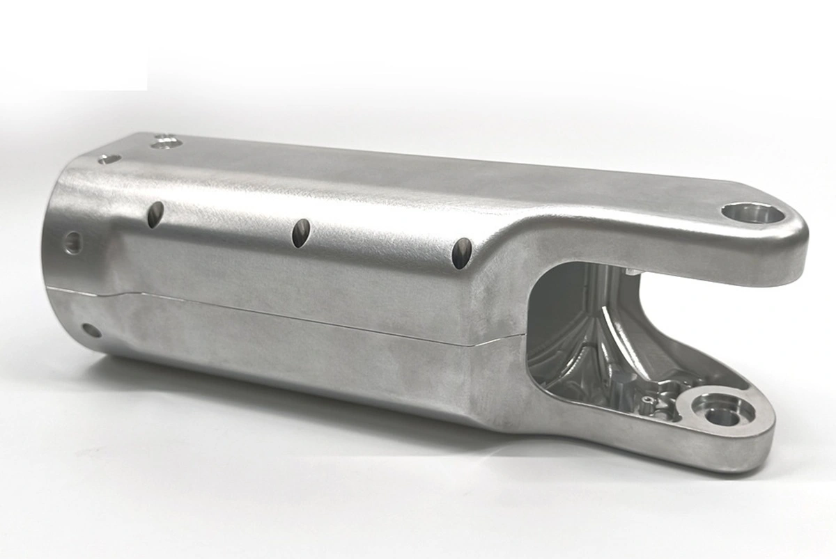
Take the mounting holes, locating features, seating faces, and fastener access from the selected gripper’s mechanical drawing. Bolt spacing is only part of the interface, because pins, sleeves, or other specified locating features set the finger’s position. Check clearance through the full jaw stroke, then use a DFM review to confirm cutter access to contact pockets, holes, and internal corners, including any radius or setup change the design needs.
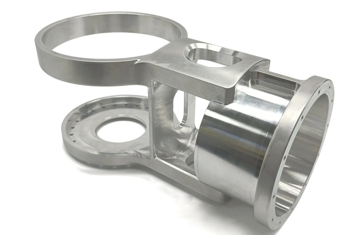
CNC Machining for Custom Gripper Fingers
CNC machining produces the mounting faces, hole patterns, and contact contours that define a custom finger. Three-axis milling handles accessible features, and indexed or five-axis machining reaches angled and multi-face geometry. Choose the process by feature access, workholding, and the relationships between critical surfaces.
Rollyu Precision machines robotics components, including end-effectors, in aluminum, stainless steel, and engineering plastics on 3-, 4-, and 5-axis CNC equipment, with early-stage DFM consultation before production. For a finger set, raise these points in that review:
- Cutter access around contact profiles and internal features
- Workholding support for thin or extended sections
- Tolerances on mounting locations and contact geometry
- Finishing allowances on functional surfaces
Put tight tolerances only where they control fit or contact. Tightening every surface to the same limit adds machining and inspection work without improving the functional interface. For coated mating faces or holes, state whether dimensions apply before or after finishing.
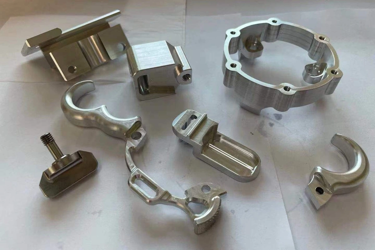
Inspecting and Testing a Custom Finger Set
Inspect the mounting locations, seating faces, and contact profiles defined on the drawing, using methods that suit their tolerances and access. Rollyu uses CMM inspection and other dimensional methods, and its dimensional reports give the engineering team a record of the manufactured geometry for assembly and acceptance.
Then run the assembled fingers with the actual workpiece through the full handling cycle, checking for slipping, interference, misalignment, and excessive loading during pickup, motion, and release. Dimensional inspection confirms the part geometry, and only installed testing shows how the fingers behave in operation.
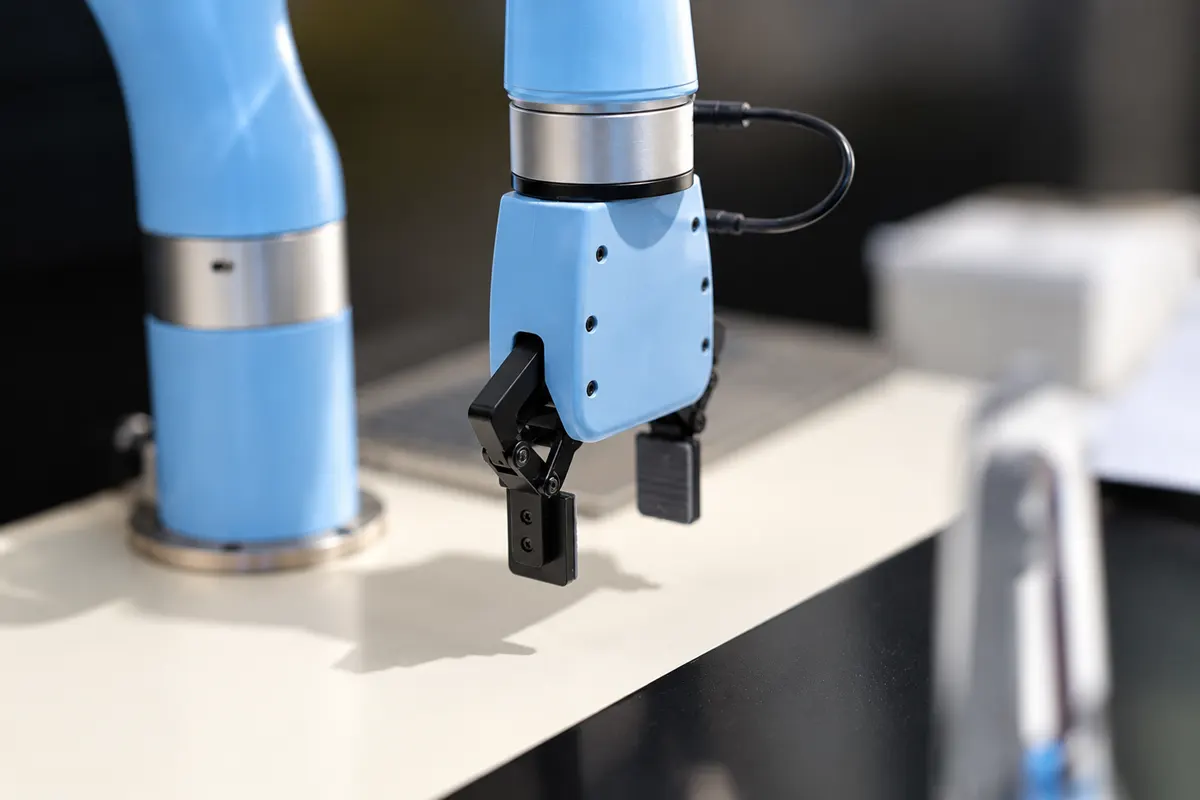
Moving From Prototype to Repeat Orders
Rollyu’s support for robotics components covers prototyping, machining in metals and engineering plastics, finishing, and low-volume production, so finger bodies and machined contact inserts can move from DFM review to repeat orders with one supplier. Use the prototype to confirm installation, contact behavior, and motion, and record approved changes in the model and drawing, including material condition, finish, and inspection requirements, before ordering again. The automation team still verifies the finger set’s behavior in the intended cell.
For DFM feedback and a custom-part quote, send Rollyu Precision:
- The finger model or drawing
- The gripper interface drawing
- Workpiece geometry
- Prototype and repeat-order quantities
Mark the mounting and contact features that control fit so the machining and inspection plan covers them directly.
Frequently Asked Questions
Can Gripper Fingers Be 3D Printed?
Yes. Printed fingers work well for early fit and motion checks, and some designs use them in service. For production, choose the printing process and material by load, geometry, and wear, then test the finished fingers in the application, since a successful fit check doesn’t show service life.
Can One Finger Set Handle Several Different Parts?
Yes, if the contact surfaces and gripper travel suit each part. Multiple gripping surfaces can serve a part family as long as every workpiece gets a secure grasp and clear approach and release paths. Use separate finger sets when the parts need incompatible contact positions.
What Determines the Cost of Custom Gripper Fingers?
Material, geometry, quantity, tolerances, finishing, and inspection requirements drive the quote, and thin sections, long reach, and difficult tool access add machining time. List prototype and repeat-order quantities separately so the quote reflects the setup and production work at each stage.