
Sheet metal fabrication turns flat sheets into functional components and parts. The process uses laser cutting, shearing, punching, stamping, bending, and welding to achieve precise geometries. Manufacturers and engineers rely on these techniques to obtain high accuracy, structural integrity, and efficiency in large-scale production.
This guide explains how to choose material thickness, design bends, place holes, and plan cut-outs to make metal fabrication. It also covers CNC sheet metal forming, waterjet cutting, CNC bending, welding, riveting, fastening, tolerance control with GD&T, and the importance of surface finishing such as powder coating, aluminum anodizing, zinc plating, electroplating, and laser marking. Our core focus is on giving engineers practical design insights to avoid problems, reduce costs, and improve manufacturability across prototypes and high-volume production runs.
Importance of Sheet Metal Fabrication
Sheet metal fabrication permeates nearly all the things around us. From robotics, renewable energy, and telecommunications to medical devices, it offers precision in all areas. You can produce complicated shapes without adding excess weight.
The process facilitates medium to large volume runs. Sheet metal can be cut, bent, punched, or welded to any specific specification. This is why it can be used in lightweight planes, protective cases, and casings of electronics and other vital parts. Moreover, the process supports customization. You can produce single prototypes or run 100s of them.
Applications for Sheet Metal Fabrication
Here are the common applications of sheet metal fabrication.
Medical Devices: Sheet metal process for medical sheet metal fabrication is used for diagnostic equipment enclosures, surgical robotics frames, dental equipment metal parts, sterilization tray, and medical carts.
Robotics: Precision robotics demand high structural integrity and accuracy in sheet metal components. Industrial robot arm covers, autonomous vehicle (AGV/AMR) frames, assembly line robotics housings, and collaborative robot (cobot) safety enclosures.
Telecommunications: Telecom infrastructure relies on rugged and scalable sheet metal enclosures, enclosure sheet metal, and sheet metal chassis for network operation.
Electronics: It helps make metal enclosures, custom sheet metal enclosures, cooling brackets, electrical junction box, aluminum enclosure, electrical enclosure, and connector panels.
Farming: Tractor hoods, metal brackets, metal enclosures, harvesting blades, outdoor junction box, and storage bins are produced by sheet metal techniques.
Energy Sector: It’s ideal for making wind turbine nacelles, solar panel frames, transformer cabinets, power distribution systems, metal generator enclosure, and battery enclosures.
Automotive Industry: It’s useful for shaping car body panels, chassis components, exhaust systems, and mounting brackets.
Aerospace Industry: In the aerospace sector, it is applied in producing lightweight aircraft skins, turbine housing, fuel tanks, satellite subsystem enclosures, and internal reinforcements.
Sheet Metal Fabrication Fundamentals
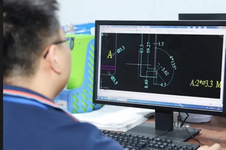
Sheet metal fabrication converts sheet metal stock into precise components. It relies on technical drawings. These files define dimensions, bend lines, and tolerances. This ensures parts are accurate, durable, and consistent for production.
Precision Cutting Methods
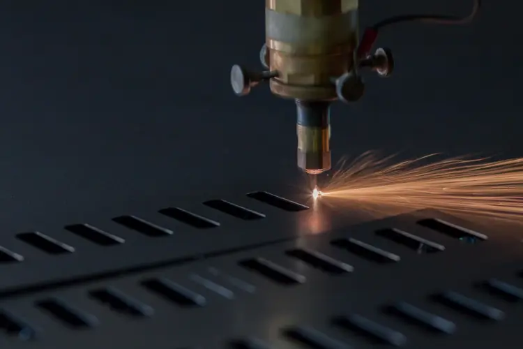
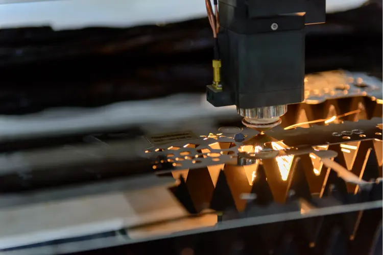
Laser Cutting: Laser cutting is a precision manufacturing process that uses a high-powered, focused laser beam to cut or engrave materials with exceptional accuracy. Laser cutting offers high precision, repeatability, and versatility for a wide range of industrial and creative applications. By understanding the core principles, selecting the right equipment, and optimizing process parameters, we can achieve excellent results on diverse materials.
Waterjet Cutting: Waterjet cutting is another highly versatile precision cutting method, often compared with laser cutting but with unique advantages. It uses an ultra-high-pressure stream of water—sometimes mixed with abrasive particles—to cut materials without generating heat. Waterjet cutting delivers precise, cold-cutting performance across a broad spectrum of materials. By understanding system components, optimizing key parameters, and adhering to best practices, you can achieve clean, accurate cuts for both industrial and creative applications.
Plasma Cutting: Plasma cutting is a thermal cutting process that uses an accelerated jet of ionized gas (plasma) to cut through electrically conductive materials. It’s widely used in metal fabrication due to its speed and cost-effectiveness for medium- to thick-gauge metals.Plasma cutting offers a high-speed, cost-effective solution for cutting a wide range of conductive metals. By selecting the right torch, gases, and parameters—and following safety protocols—you can achieve efficient, accurate cuts for industrial and creative projects alike.

Controlled Bending and Forming
Sheet Metal Bending converts flat sheets into 3D components like metal panels, metal enclosures, metal brackets, and metal frames. Press brakes are employed in this process. These machines manufacture precise angles on panels, brackets, and frames. Bending has two types in general:
Roll bending: It creates smooth, curved shapes.
Air Bending: It is flexible and optimal for prototypes. You can gain accurate bends to ensure parts fit well and are easy to maintain.
Joining Techniques
Joining combines sheet metal parts into strong assemblies. Permanent, high-strength bonds are produced by welding. Riveting is a non-heat way of securing parts. Usually, it is used for disassembly purposes. Mechanical fasteners are used to prevent misalignment.
Surface Finishing Treatments
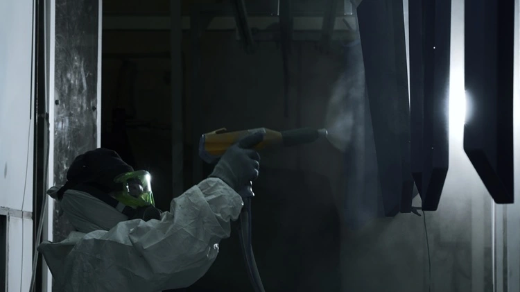
Finishing promotes the durability, longevity, and corrosion-resistant abilities of the sheet metal parts. Some of the common techniques include: Powder coating, anodizing, electroplating, and laser marking etc.
Powder coating is a highly durable and eco-friendly finishing process used to apply a protective and decorative coating to metal components. Unlike wet painting, it uses dry, electrostatically charged powder that is fused to the surface under heat, forming a continuous and robust film.
Anodizing is an electrochemical surface treatment process that enhances the natural oxide layer on metals—primarily aluminum—to improve corrosion resistance, wear resistance, and appearance. It’s widely used in medical devices, electronics, aerospace, automotive, and precision engineering due to its durability and aesthetic flexibility.
Electroplating is a surface finishing process that deposits a thin layer of metal onto a part using an electrical current. It is widely used to improve corrosion resistance, wear resistance, electrical conductivity, solderability, and aesthetics
Laser marking is a precision process used to permanently mark or engrave materials with text, serial numbers, logos, barcodes, QR codes, and other identification features.
The right finishing technique ensures durability and reliable performance.
Material/Tolerance Management
Strength, weight, and functionality are influenced by material choice.
Steel Sheet Metal Fabrication is the process of converting flat steel sheets into functional parts and assemblies through cutting, bending, forming, welding, and finishing operations.
Aluminum Sheet Metal Fabrication refers to the processes used to cut, bend, join, and finish aluminum sheets into functional components or assemblies. Aluminum is a popular sheet metal material due to its lightweight, corrosion resistance, excellent strength-to-weight ratio, and good formability
Stainless Steel Sheet Metal Fabrication involves transforming flat stainless steel sheets into durable and precise components through cutting, bending, welding, and finishing processes. Stainless steel is highly valued for its corrosion resistance, strength, and clean appearance, making it ideal for industries such as medical devices, food processing equipment, aerospace, robotics, and semiconductors.
Design Guidelines and Practical Techniques
Proper design is fundamental in sheet metal fabrication. It ensures parts are strong, functional, and manufacturable. Here are the technical guidelines to help you prevent errors, reduce waste, and maintain production efficiency.
Bend Radius
In sheet metal fabrication design, keep the bend radius minimum. It usually varies with the thickness and material type chosen. In the case of steel, the radius must be at least 1 to 1.5 times the material thickness. The bend radius for aluminum should be 1 to 2 times the material thickness. Bend radius prevents stress concentration and bend fatigue.
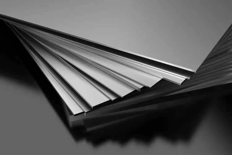
Material Thickness Considerations
The right thickness is a matter of strength/weight balance. Steel sheets normally come between 0.5mm and 6 mm for brackets and panels. Aluminium sheets commonly utilize 1mm to 5mm as a lightweight component. The right thickness will mitigate bending and part vibration. It also minimizes excessive material expenses.
Tolerance and Allowance
The standard sheet metal tolerance is about +/-0.1mm on precision parts and +/-0.5mm on general panels. Bend allowance refers to an allowance to accommodate stretching and compression in bending. Accurate calculations of tolerance and allowance will prevent missing and misalignment in assemblies.
Hole/Slot Design
The hole diameter must not be too large, because it leads to deformation during punching and laser cutting. For sheet metal, fastener holes are usually 0.1 to 0.5 mm larger than the fastener to allow a right fit. Slots must be rounded on the ends to avoid tearing under stress. Proper hole and slot design will support easy assembly and long service life of the parts.
Cuts and Notches Relief
Stress-relieving alleviates stress at corners and bends. Cut lengths on typical relief are 1 to 2 times the sheet thickness. Notches facilitate complex shapes without causing cracks in the material. While reliefs improve bend quality and eliminate part distortion.
Grain Direction and Orientation
Metal sheets bend and hold strength along their grain direction. Bends across the grain have less tendency to crack. Placement of parts with the grain also gives better mechanical properties and avoids surface defects.
DFM Tips for Sheet Metal Fabrication Design
Designing sheet metal parts with DFM principles helps metal fabrication design engineers reduce costs, improve manufacturability, and ensure reliable, repeatable production. Below are key considerations when creating sheet metal components
Material Selection
Choose the right material grade early: Stainless steel, aluminum, and mild steel have different bendability, corrosion resistance, and cost profiles.
Consider thickness consistency: Use standard sheet thicknesses available in your region to avoid custom material lead times.
Balance strength vs. weight: For aerospace or medical housings, aluminum may reduce weight while stainless ensures durability.
Optimize Bend Design
Minimum bend radius: A general rule: Bend radius ≥ sheet thickness (often 1× to 3× material thickness depending on alloy). Too-tight bends cause cracking or warping.
Bend relief: Add relief slots near bends to prevent tearing. Relief slot depth should exceed the bend radius plus material thickness.
Consistent bend orientation: Design bends in the same direction to reduce setup time.
Account for bend allowance/K-factor: Ensure flat patterns consider stretching during bending to maintain dimensions.
Hole and Feature Placement
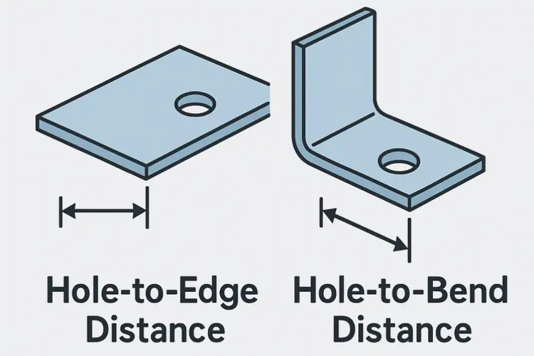
Distance from edge: Holes should be at least 2× material thickness away from edges or bends to prevent distortion.
Hole diameter: Minimum hole diameter should be ≥ material thickness.
Avoid placing holes across bends: Unless planned for post-bending drilling.
Use standard hole sizes: Align with available punch tooling to reduce cost.
Maintain Uniform Wall Thickness
Avoid unnecessary thickness variation; it complicates bending and increases cost.
Use gussets or ribs instead of increasing thickness for added strength.
Minimize Welds Where Possible
Use tabs, slots, and self-locking designs to reduce welding needs.
If welding is required: Provide adequate clearance and access; design joints with minimal distortion risk.
Standardized Features
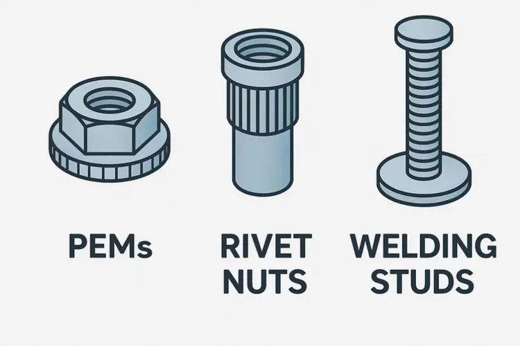
Use standard fastener holes (for PEM inserts, screws, rivets) and common hardware sizes.
Use modular design concepts: multiple parts share the same brackets or panels to re duce tooling.
Allow Adequate Tolerances
Avoid unnecessarily tight tolerances; consult your fabricator for realistic limits.
Typical laser-cut feature tolerance: ±0.1 mm.
Bend angle tolerance: ±1–2°.
Tight tolerances on non-critical features increase inspection and production cost.
Countersink for Sheet Metal Fabrication
Countersinking in sheet metal processing creates a conical recess around a hole so that a flat-head fastener (screw or rivet) sits flush or below the part’s surface. Proper countersink design and execution improve assembly appearance, reduce snag hazards, and help distribute clamping loads. This guide covers countersink in sheet metal parts design considerations.
Design Considerations:
- Sheet Thickness vs. Countersink Depth
– Keep countersink depth (d) ≤ 80% of sheet thickness (t) to preserve strength and avoid cracking.
– Example: For t = 2.0 mm, maximum recess depth ~1.6 mm. - Fastener Head Geometry
– Match the conical angle of the countersink to the fastener:
• Common angles: 82°, 85°, 90°, 100°, 110°
• Example: ANSI B18.6.3 flat-heads typically use 82° countersinks. - Hole Size and Tolerance
– Initial hole diameter (before countersinking) should match the fastener’s minor diameter or pilot-hole recommendation.
– Typical clearance: +0.1 mm to +0.2 mm on the screw shank. - Edge Distance and Concentricity
– Maintain at least two hole-diameters distance from part edges to prevent “tear-out.”
– Ensure countersink is concentric with the hole; use proper fixturing or guide bushes.
Countersinking sheet metal is a straightforward operation—but success depends on thoughtful design, proper tooling, controlled processes, and diligent inspection. By matching your countersink angle and depth to the fastener, using pilot-guided tools or form dies, and monitoring quality with simple gauges, you’ll achieve flush-mounted hardware, strong clamp loads, and professional appearance in every fabricated part.
Finishing Considerations
Plan for powder coating sheet metal fabrication, anodizing metal fabrication, or passivation sheet metal fabrication early.
Include masking zones or hanging holes in the design.
Ensure finishing does not alter functional tolerances (e.g., coating buildup).
Design for Assembly
Ensure parts self-align with tabs or locating features.
Avoid hidden fasteners that complicate assembly.
Provide adequate clearance for tools and operator hands.
The Package Design for Sheet Metal Parts
When we talk about package design for sheet metal parts, the key is balancing protection, efficiency, and presentation. Since sheet metal parts are often fragile (susceptible to scratches, dents, corrosion, and deformation), packaging design must prevent damage during handling, storage, and transport. Below I’ll outline the main elements:

Quality Control & Technology Trends
Sheet metal fabrication is evolving rapidly under pressure for higher quality, shorter lead times, and smarter workflows. Strict quality controls determine that each part meets design and functional requirements. It prevents failures, minimizes waste, and optimizes production.
Raw Material Inspection
Raw materials inspection is the first and one of the most critical stages in ensuring high-quality sheet metal fabrication. The inspection is checked for thickness, composition, and surface defects. Steel and aluminium sheets are measured with micrometers and tested for hardness. By verifying material properties before production begins, metal fabrication manufacturers can prevent costly rework, compliance issues, and performance failures in the final product.
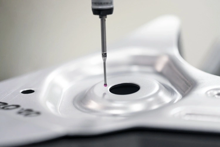
Dimensional Accuracy Checks
In sheet metal fabrication techniques, metal fabrication parts are gauged on length, width, bend angle, and hole locations. Tolerances are checked using calipers, coordinate measuring machines (CMM), or laser scanners. It may be as tight as ±0.1mm for precision parts. Accurate measurements make components fit well on assemblies. Even a fraction of a millimeter can determine whether a part integrates seamlessly into an assembly or becomes unusable. For industries like medical devices, semiconductor manufacturing, and robotics, tight tolerances are non-negotiable. ISO 13485 and ISO 9001 standards explicitly require documented proof that fabricated components meet all dimensional specifications.
Incorrect dimensions can lead to:
- Assembly failures due to mismatched parts
- Stress concentration causing premature wear or failure
- Regulatory non-compliance, particularly in medical devices
- Cost overruns from rework or scrap
- Delayed production schedules, impacting downstream customers
For fabrication of sheet metal parts. This makes dimensional inspection in one of the most critical stages in a quality control program.
Weld and Join Verification
Welded or riveted assemblies are checked to eliminate nonuniformity and ensure strength. The cracks and weak spots are detected by visual checks, ultrasonic testing, or X-ray inspection. In precision sheet metal fabrication, welding and joining processes are critical to both structural integrity and functional performance. Poorly executed welds or joins can lead to:
- Mechanical failures due to stress concentration or weak bonds
- Misalignment of mating parts, impacting assembly
- Surface defects that compromise finishing processes like anodizing or powder coating
- Regulatory non-compliance, particularly in medical devices governed by ISO13485
- Reduced product lifespan in high-performance robotics or semiconductor applications
Effective weld and join verification ensures that parts not only meet dimensional and functional requirements but also comply with industry-specific standards, from ISO 9001 to ISO13485, and AWS codes.
Surface and Coating Evaluation
Evaluating surfaces and coatings is critical in sheet metal manufacturing. Thickness, adhesion, and smoothness of surface treatment such as powder coating, anodizing, or galvanising are examined. Corrosion protection and aesthetic quality are provided by roughness testers and by visual inspection. These treatments extend the part’s life and improve performance.
Final Functional Testing
Key components are tested under loads, stress, or vibrations. Simulated conditions confirm that parts work as intended. Functional testing ensures reliability with critical applications, such as robotics, telecom, aerospace, automotive, and medical equipment.
When it comes to technological trends, sheet metal fabrication is evolving rapidly. Modern metal fabrication shops are now employing advanced tools and techniques. For instance, these advancements involve.
Final functional testing (FFT) verifies that a finished assembly or product operates correctly under its intended conditions. By combining performance checks with environmental and safety evaluations, FFT ensures customer requirements are met and reduces the risk of field failures.
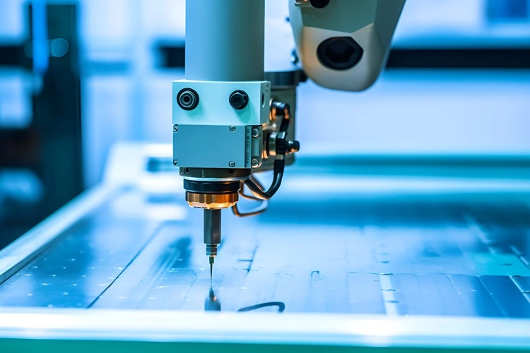
CNC Automation
CNC machining service automates cutting, bending, and punching with high precision. These reduce manual intervention and increase production repeatability. Computer Numerical Control (CNC) automation integrates advanced robotics, material‐handling systems, and intelligent software with traditional CNC machine tools to achieve higher throughput, tighter tolerances, and lights‐out production. Modern CNC setups can handle batch production with complex designs efficiently.
CNC Laser Cutting and Waterjet Cutters
CNC laser cutting and waterjet cutting technologies have revolutionized precision sheet metal fabrication by enabling high-precision, high-complexity cuts with minimal material waste. Their adoption is critical for industries like medical devices, semiconductor equipment, and robotics, where tolerances are tight and part geometries are intricate. CNC Laser cutting gives fine edges with minimal heat distortion. Water jet cutting handles thick and heat-sensitive materials. Both sheet metal fabrication techniques reduce waste and allow intricate patterns that conventional tools cannot achieve.
3D Simulation and CAD Integration
Now, designs are modelled digitally before production. Simulations pinpoint bending behaviour, stress points, and material usage. CAD integration increases accuracy from prototype to full-scale production.
In precision sheet metal fabrication, errors in design or manufacturing setup can lead to material waste, assembly misfits, and regulatory non-compliance. Integrating 3D simulation and CAD (Computer-Aided Design) models into production enables:
- Early detection of design issues before physical production
- Validation of bends, folds, and cutouts against tolerances
- Optimized tooling paths for CNC laser, waterjet, or punch machines
- Integration of QC checkpoints digitally for faster inspection
- Reduced rework, scrap, and lead times, which is critical for high-precision industries like medical devices, semiconductors, and robotics
Customer Service and Commitment
Good customer service starts with understanding your product or parts design needs. Rollyu takes time to listen and clarify every detail. Ensuring your parts are exactly what you expect. Support continues through the whole process. From design advice to choosing materials and sheet metal fabrication techniques, we guide you at every step. This helps avoid mistakes and saves time.
Commitment means reliability you can trust. Each part is carefully manufactured and inspected to meet quality and performance standards. Deadlines are respected, and any issues are handled quickly. By focusing on service and dedication, our clients receive more than just parts; they get practical solutions that are efficient, durable, and ready to perform.
Conclusion
Sheet metal fabrication makes strong and precise parts for many industries. It is used in medical, robotics, automotive, aerospace, electronics, telecommunications, and renewable energy. Using the right design and metal fabrication techniques ensures accuracy and durability. Quality checks at every step improve performance and reliability.
Modern tools like CNC laser cutting machines, metal bending machines, punch machines, riveting machines, and press brakes allow complex shapes and faster production. Choosing the right material and thickness keeps parts strong but lightweight. For best results, plan your design carefully, test prototypes, and follow quality standards. This ensures parts are efficient, durable, and suitable for their intended use.