
CNC Machining Dot Code Calibration Aluminum Plate
At first glance, this CNC machining part might look quite simple, right? We thought so too when we first received the drawing for a CNC online quote. However, after carefully evaluating the prints, we quickly realized that manufacturing this CNC part was anything but simple.
When the customer reached out to us, they asked several questions and provided the following context:
“This part will be used to validate the measurements of our optical metrology system meant to perform metrology on such elevated characters. We will send the parts to a certified metrology laboratory to have the dimensions of the 3 letters (D O T) to be measured. We do not need the dimensions to be extremely accurate, since we will calibrate on the dimensions of the metrology laboratory. However, we do need to have very precise parallelism and flatness of the surfaces in the area of the detail view. This is why we ask that you pass with the same finishing milling head on all the region in detail view. Do not debur the 3 letters. This is the important region. Note that our other 3 suppliers do a slight sandblast on the parts so they get back a dark black, we do not like their job. I saw your regular precision CNC machining parts, and I think your standard surface finishing and anodizing process will be better for this part, so we found you to make these CNC machining parts.
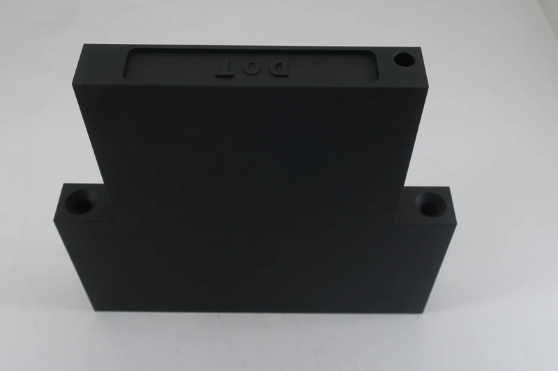
The customer also mentioned that they had previously tried three other suppliers without success, and asked if we were confident we could produce it. Our response was resolute: “We are absolutely confident we can manufacture these machined parts.”
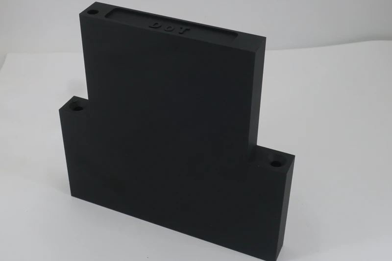
Through our initial communication, we understood that this part is used strictly for calibrating an optical measurement system (not a structural assembly component). Therefore, the primary focus wasn’t on standard dimensional tolerances, but on flatness, parallelism, and surface consistency within 0.01mm. The raised “D O T” letters are the measurement targets, not functional features. For this project, surface behavior took absolute precedence over basic geometry.
Project Overview
- Customer Location: Canada
- Customer Industry: 3D Machine Vision and Surface Inspection Systems
- Customer Project: Optical Metrology System
- Application: Optical Metrology Calibration
- Material: Aluminum 6061-T6
- Surface Finish: Sand Blast + Black Matte Anodize, MIL-A-8625F Type II Class 2
Why This Part Is Difficult and How We Solved It
Manufacturing this aluminum calibration plate prioritizes strict optical-grade surface behavior over standard geometry.
Securing flatness and parallelism within 0.01mm across the critical D O T zone requires a continuous, single-tool finishing pass. Operators must prevent step formations and retain perfectly sharp micro-letter edges. Manual deburring alters edge geometry and is strictly prohibited during the surface finish stage.
Producing a white-film-free matte black anodized surface demands precise control over sandblasting impact and caustic etching duration. Protecting delicate character edges through this chemical treatment requires final validation via laboratory-grade metrology reporting rather than standard quality control.
The “D O T” Detail View Area
The Requirements:
- The drawing explicitly stated: “USE THE SAME MILLING HEAD FOR FINISHING PASS ON ALL THE DETAIL VIEW AREA.”
- Internal Manufacturing Requirements: No tool changes allowed while finishing this area. The entire detail view must be completed in a single continuous pass using the same tool length compensation, the same tool, and the same program block.
- Goal: Avoid any steps, overlapping tool marks, or transition lines.
The Challenge:
This is the customer’s critical metrology area. The geometric tolerance for flatness and parallelism is exceptionally strict. While the exact dimensions of the letters themselves didn’t require extreme precision, the surface flatness around them had to be flawless.
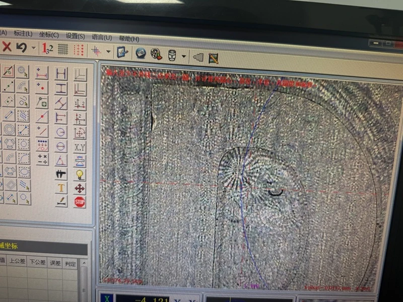
Our Solution:
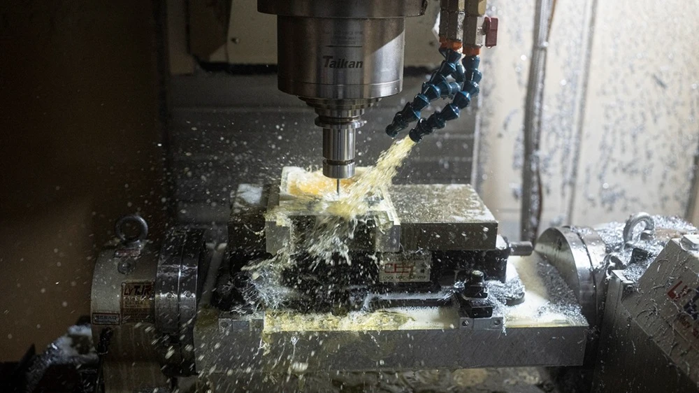
- Rough Machining and Stress Relief: Starting with 6061-T6 aluminum blanks, we utilized 4-axis CNC milling, strictly controlling symmetrical material removal to prevent warping, leaving a 0.2 – 0.3 mm allowance. To mitigate internal material stress, we added a stress-relief process after roughing before moving on to finishing. First, we milled the reference planes and edges to establish repeatable datum points.
- Semi-Finish Machining: We semi-finished the surrounding areas, leaving just 0.02–0.05 mm for the final finish pass. This prepared the surface for the critical “single-pass finish.”
- Final Finishing: To comply with the “same milling head” requirement, we used a brand-new, highly stable Ø6 flat end mill. We utilized a one-directional pass (no zig-zagging, no crossing tool marks) to ensure the surface had zero steps, zero chatter marks, and uniform reflectivity.
- Speed:12000–16000 rpm
- Feed rate:800–1200 mm/min
- Letter Machining (D / O / T): Using 2.5D contour milling with Ø1–Ø2 mm micro end mills, we machined the raised characters. Because the customer emphasized “Do not debur the 3 letters,”we carefully cleared the surrounding material while preserving the sharp edges. Absolutely no manual deburring, brushing, or light polishing was allowed.
Surface Finish
The Challenge:
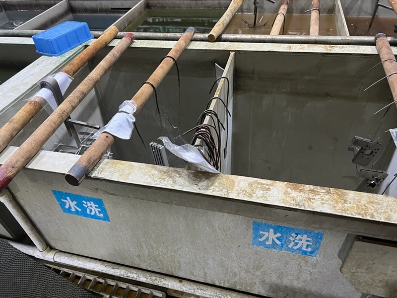
The drawing required Sand Blast + Black Matte Anodize (MIL-A-8625F Type II Class 2). The customer specifically needed the parts to stay in the caustic etch longer to remove all sand residue, ensuring a deep black finish without any “white film” artifacts.
Our Solution:
- Applied a light sandblast using a finer grit.
- Strictly controlled the blasting impact pressure around the letter area to prevent dulling the sharp edges.
- Extended the cleaning and caustic etching time before anodizing to thoroughly remove residual sand and eliminate any risk of a white film.
Focused on the overall consistency of the matte black finish across the entire part, not just localized areas.
Inspection Procedure
The Challenge:
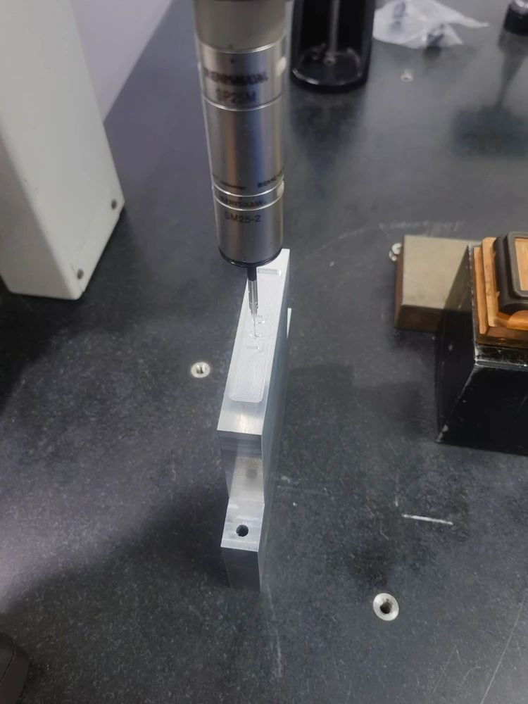
The blueprint clearly stated: “METROLOGY PROCEDURE FOR THE DOT CODE CALIBRATION PLATE FOR FTI 2.0. REPORT ALL VALUES AND INSTALL CALIBRATION LABEL.” This meant standard Outgoing Quality Control (OQC) was insufficient; we had to output exact measurement results corresponding to specific views on the drawing.
Our Solution:
We divided the inspection into two stages:
- Pre-Anodizing Inspection: Using a CMM and height gauges to verify the critical area geometry, letter formation, hole positions, and overall dimensions.
- Post-Anodizing Inspection: Re-verifying surface appearance, blackness consistency, checking for white film, and ensuring the sharp edges of the letters were intact. Finally, we compiled the data into a formal metrology report based on the specific sectional views on Page 2 of the drawing, and applied the calibration labels as requested.
Why Choose Rollyu Precision?
Rollyu Precision manufactures optical calibration plates by integrating stress-relieving roughing with lab-grade CMM metrology. Securing 0.01mm surface consistency dictates a highly controlled, continuous single-pass finishing strategy.
Operators apply micro-milling techniques to generate sharp, burr-free characters. Eliminating manual intervention entirely protects fragile edge geometries. Maintaining strict control over the MIL-SPEC black matte anodizing process prevents white-film artifacts and stabilizes the final optical finish.
Validating complex optical components requires strictly controlled manufacturing environments rather than standard quality checks. Submit your RFQ to secure custom CNC machining and certified metrology reporting for your technical projects.
| Manufacturing Process Routing / Traveler | ||||
| Op No. | Operation Name | Equipment / Fixture/Tooling | Process Description | Key Control Points/ Inspection Requirements |
| OP00 | Material Prep & Sawing | Band Saw Standard Saw Blade |
Cut AL 6061-T6 stock. Leave allowance on all sides and thickness for clamping. | Raw material must not be bent or dented. Verify raw material cert. & visual check. |
| OP10 | Establish Primary Datum | VMC + Vise / Clamps Face Mill, Ø10~12 Flat End Mill |
Rough & finish mill the first surface to establish the primary datum plane; then machine two mutually perpendicular datum edges. | Datum planes must be flat and stable without obvious chatter marks. Self-check primary datum flatness & perpendicularity. |
| OP20 | Flip & Machine Total Thickness/Profile | VMC + Vise / Soft Jaws Face Mill, Flat End Mill |
Flip part, machine to drawing thickness/steps. Rough and finish overall outer profile as per drawing. | Maintain a stable clamping surface for the subsequent Detail View machining. Spot check total thickness and profile dimensions. |
| OP30 | Hole & General Feature Machining | VMC + Locating Fixture Spot Drill, Drill, Counterbore / End Mill |
Machine 2X Ø6.6 THRU holes and related counterbores. Machine other general features per drawing. | Burrs from holes must NOT fold into the critical area. Verify hole diameters, locations, and counterbore specs per drawing. |
| OP40 | Detail Area Roughing & Semi-Finishing | VMC + Dedicated Fixture Plate / Vacuum Chuck (Preferred) Micro Flat End Mill |
Rough and semi-finish the Detail View area. Leave a uniform 0.02~0.05 mm allowance on all final surfaces. | Only leave allowance here, DO NOT perform final finish cut. Avoid premature deburring. Visually check for uniform allowance and no tool collision. |
| OP50 | Detail Area Final Finish Machining | VMC + Stable Fixture Single Final Finishing Tool: Micro Flat End Mill |
Use the SAME finishing tool to complete the final pass for the entire Detail View area. Must be completed continuously using the same tool, same tool offset, and same program block. | STRICTLY PROHIBITED: Tool changes, offset adjustments, or sectioned finishing. NO STEPS ALLOWED. One-directional pass recommended; avoid cross-hatching marks. Verify surface continuity in critical area (no steps); Ensure critical geometric tolerances meet drawing. |
| OP60 | D / O / T Letter Profiling | Same setup as OP50 Same final tool as OP50 (preferred). Pre-roughing done in OP40. |
Final profile/periphery of letters must be completed along with the Detail area. No secondary manual deburring allowed after machining. | STRICTLY PROHIBITED: Deburring, polishing, or edge-rounding in the D/O/T area. Visually check letter boundaries for integrity; no chipping. |
| OP70 | Non-Critical Area Deburring | Workbench / Deburring Station | Break sharp edges ONLY outside of the Detail View area. | DO NOT touch the Detail View area. Edge-breaking must not extend into the letter area. 100% Visual Inspection. |
| OP80 | Pre-Treatment Inspection | CMM / Height Gauge / Optical Comparator Scraper, Whetstone, Chamfer Tool |
Inspect overall dimensions, holes, and the flatness/consistency of the critical area before surface treatment. | Parts failing the critical area inspection must NOT proceed to surface treatment. 100% CMM inspection recommended for First Article. |
| OP90 | Sand Blast + Black Matte Anodize | Outsourced Surface Treatment Sandblasting / Anodizing Line |
Light sandblast followed by black matte anodizing (MIL-A-8625F Type II Class 2). | Caustic etch time must be longer than standard. Final product must be deep black with NO white film. Final visual check for appearance, color, and coating quality. |
| OP100 | Final Inspection / Metrology Report / Labeling | CMM / QC Dept. Metrology Equipment |
Output results according to the “metrology procedure” on Page 2, report all values, and apply calibration label. | Page 2 is the mandatory inspection reference and must be strictly followed. Verify final inspection records and applied labels. |
Conclusion
To summarize our machining strategy for this part in one sentence: Rough machining to establish shape, precision machining to set datums, a single continuous tool pass for the critical surface, preserving sharp edges on the letters, applying a flawless matte black finish, and generating a rigorous metrology report.
The true challenge of this project wasn’t simply “whether it could be milled,” but guaranteeing absolute surface consistency and geometric stability in the critical metrology area. We successfully delivered on all fronts, providing the exact standard the customer needed to calibrate their optical systems.
Client Feedback
“The precision and surface consistency Rollyu delivered on this calibration plate were exactly what we needed for our optical metrology system. Since partnering with Rollyu Precision, we have complete peace of mind. We now confidently entrust all our machining and production projects to their team.”