
According to Grand View Research, the demand for industrial automation and precision components is growing. This trend highlights the need for high-performance gears capable of handling tight tolerances. In such complex systems, relying on generic, stock components can introduce performance limitations. Engineers often require gears that deliver precise torque and vibration control to help minimize costly system failures.
This guide covers key gear types, from spur to worm drives, focusing on efficiency and manufacturing feasibility. We compare key materials like 17-4PH steel and PEEK to help you balance strength with performance. Finally, you will see why CNC machining outperforms traditional methods for producing complex, custom gears.
What Is a Gear and How Does It Work?
A gear is a toothed wheel that transmits motion and torque between shafts. Unlike friction-based belts, gears use positive engagement to prevent slippage. This design ensures consistent synchronization, making it essential for high-load industrial applications.
Gears use gear ratios to modify output. The relationship between speed and torque is inverse: driving a larger gear multiplies torque but reduces speed. Driving a smaller gear increases speed but lowers torque. This allows engineers to balance force and velocity without changing the power source.
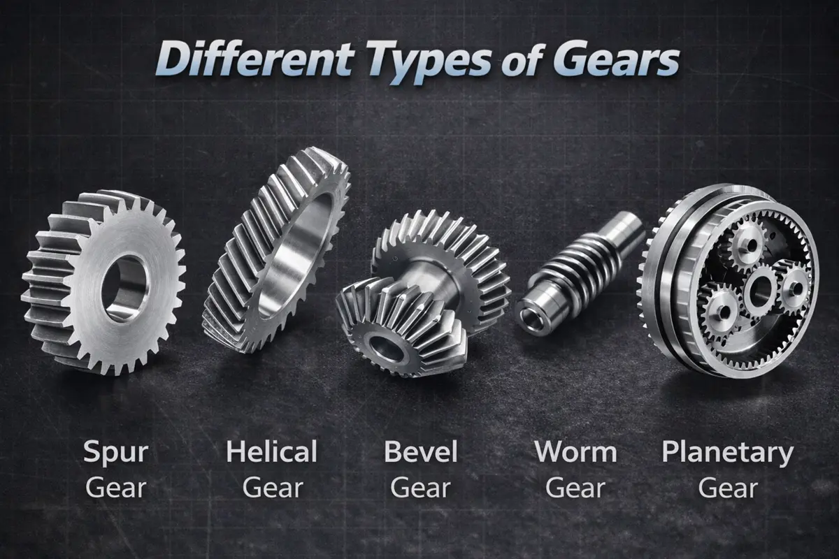
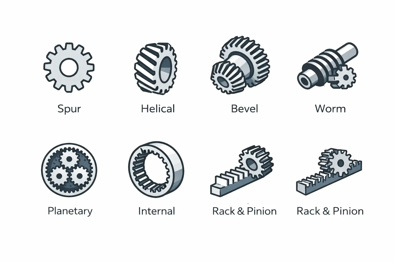
What Are the Different Types of Gears?
Engineers select gear types based on specific constraints like space, load capacity, and operating speed. Each design offers distinct mechanical advantages.
Spur Gears
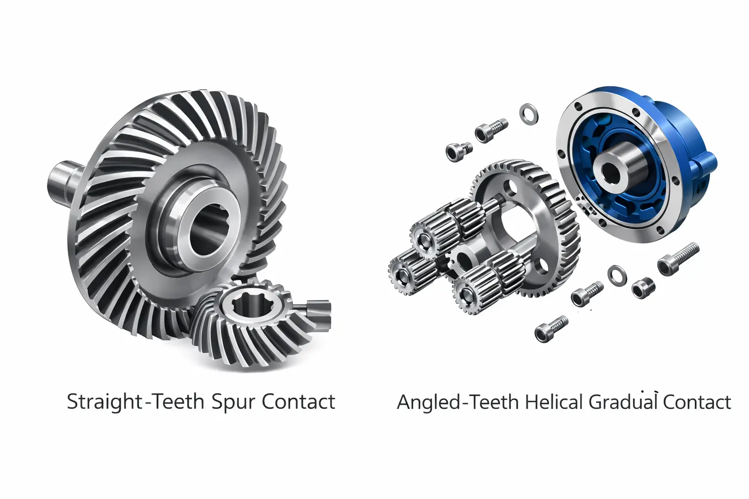
Spur gears have straight teeth on parallel shafts. They are cost-effective due to simple manufacturing. However, sudden tooth contact generates noise and vibration, restricting them to lower speeds.
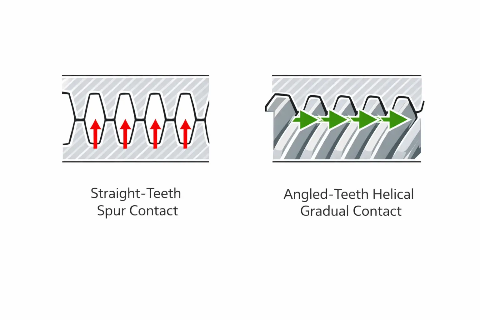
Helical Gears
Helical gears use angled teeth for gradual contact. This results in smoother and quieter operation than spur gears. The increased tooth surface area also supports higher loads and torque.
Bevel Gears
Cone-shaped bevel gears transmit power between intersecting shafts, usually at 90 degrees. They primarily change the direction of shaft rotation. Straight bevels are simple but loud, while spiral bevels run smoother under high torque.
Worm Gears
Worm gears drive a toothed wheel using a screw-like shaft. They provide high speed reduction in a single step, often up to 100:1. The design includes a self-locking feature where the input drives the output, but not vice versa.
Planetary Gears
Planetary gears use a central sun gear to drive multiple surrounding gears. This distributes the load to provide high torque in a compact design. Their low backlash makes them ideal for precision robotics and servo systems.
Internal Gears
Internal gears have teeth on a ring’s inner surface and pair with a smaller external gear. Often used as the outer ring in planetary systems. This design reduces the distance between shaft centers. It creates a compact assembly suitable for tight spaces.
Rack and Pinion
Rack and pinion systems convert rotational motion into linear travel. A circular pinion engages a flat, toothed rack. As the pinion spins, it drives the rack in a straight line for precise positioning.
How to Choose the Right Material for Precision Gears?
Material choice dictates gear lifespan. Engineers must balance load capacity with environmental factors like heat or moisture. An incorrect choice leads to broken teeth or system failure.
Metal Alloys for Strength and Durability
Metals dominate applications requiring high torque where plastics would deform. They withstand shock loads (sudden impact) and heat that would melt softer materials.
- Stainless Steel (17-4PH): Combines high strength with corrosion resistance. It suits sterile settings, such as medical devices or food machinery, where rust is a failure point.
- Alloy Steel (4140): Known for impact toughness. Engineers often compare 4140 vs 4130 steel, choosing 4140 to handle the constant stress and wear found in automotive and heavy industrial equipment.
- Titanium (Grade 5): Offers a superior ratio of strength to weight. Engineers use it in aerospace and robotics to cut weight without losing durability.
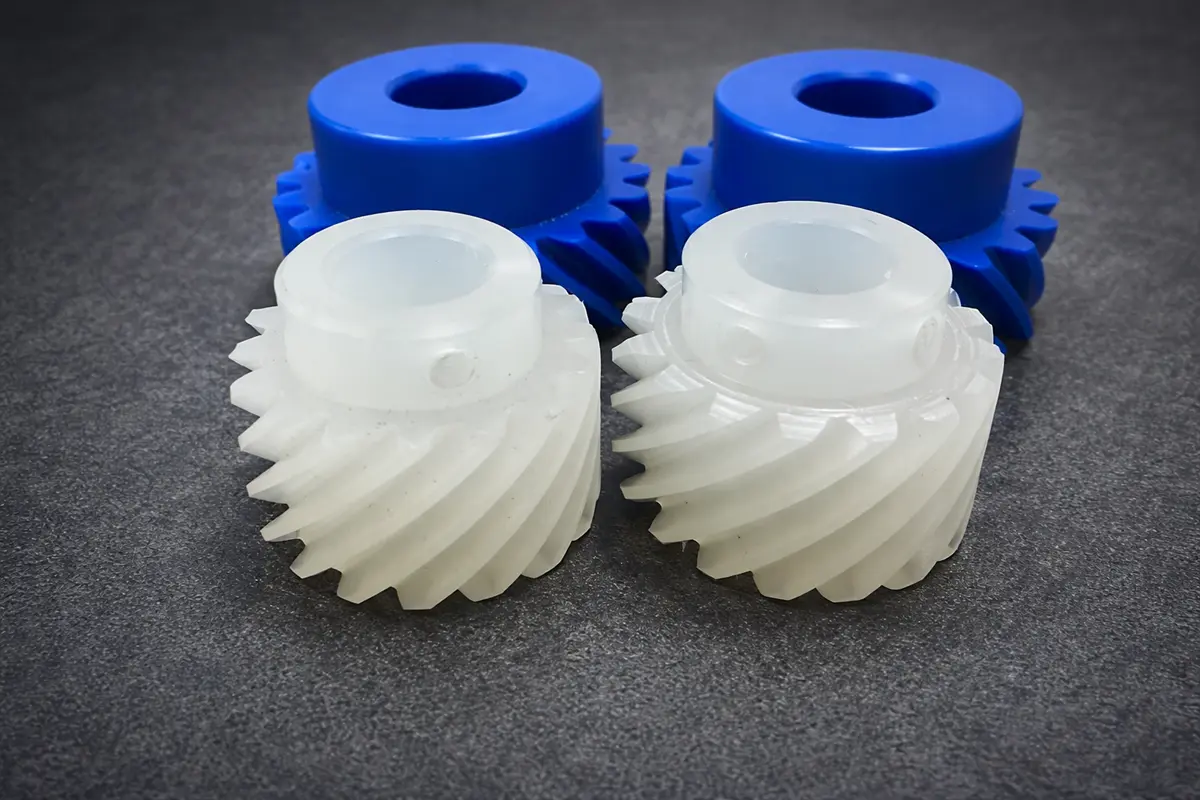
Engineering Plastics for Quiet Operation
Plastic gears run quietly and often need no external lubrication. They suit lighter loads requiring precision rather than raw power.
- POM (Acetal/Delrin): Provides stiffness and holds its precise shape over time. Comparing acetal vs delrin reveals key differences in porosity and strength that affect long-term dimensional stability.
- PEEK: An advanced plastic that withstands extreme heat and chemicals. It replaces metal in aerospace and medical tools where weight is important.
Material Selection Table
This table provides a quick reference to match material properties with specific industrial needs.
|
Material |
Key Characteristic | Best Use Case | Cost Factor |
|
Stainless Steel (17-4PH) |
High strength corrosion resistance | Food processing, Medical devices | High |
| Alloy Steel (4140) | High toughness and impact resistance | Heavy machinery, Automotive |
Medium |
|
Titanium (Grade 5) |
High strength-to-weight ratio | Robotics, Aerospace | Very High |
| POM (Delrin) | Low friction and high stability | Printers, Consumer electronics |
Low |
|
PEEK |
High heat and chemical resistance | Surgical tools, Aircraft components |
High |
What are the Differences between Types of Gears?
Selecting a gear type requires balancing efficiency, noise, and cost. Use this comparison to match mechanical properties with your specific manufacturing constraints.
|
Gear Type |
Shaft Arrangement | Pros | Cons | Manufacturing Method | Cost |
|
Spur |
Parallel | High efficiency; Simple design | High noise and vibration | Hobbing or Wire EDM | Low |
| Helical | Parallel | High load capacity; Quiet operation | Creates axial thrust | CNC Hobbing (Swivel head) |
Medium |
|
Bevel |
Intersecting (90°) | Changes drive direction | Sensitive to alignment | 5-Axis Milling | High |
|
Worm |
Non-intersecting | High reduction ratio; Self-locking | Low efficiency (Heat) | Hobbing or Thread Milling | Medium |
| Planetary | Coaxial | High torque; Compact | Complex assembly | Gear Shaping or Hobbing |
High |
|
Internal |
Parallel (Inside) | Compact; Guarded teeth | Hard to lubricate | Gear Shaping or Broaching | High |
|
Rack and Pinion |
Rotary to Linear | Precise linear positioning | Susceptible to backlash | Milling or Broaching | Medium |
What Are the Applications of Different Gear Types?
Gear application depends on specific operational demands. These range from silence for passengers and precision for robots to hygiene for surgery.
Robotics and Automation
Precision robotics parts manufacturing enables robotic arms and automated assembly lines to achieve high torque density and zero backlash, preventing jittery operation. Engineers often replace standard gears with planetary or strain wave gears. These compact designs provide the high reduction ratios and precise positioning needed to hold heavy payloads with pinpoint accuracy.
Automotive and Transportation
Passenger vehicles use helical gears for silent highway operation, while racing cars demand the raw durability of straight-cut spur gears. Although louder, spur gears transmit power more efficiently. They also withstand the extreme shock loads of rapid shifting without generating axial thrust.
Industrial Machinery and Conveyors
Factory floors value reliability. Worm gears are the top choice for conveyors because their self-locking property prevents back-driving during power cuts. In contrast, packaging lines rely on spur gears for synchronized timing. This ensures boxes move at the exact speed needed for filling and sealing.
Medical and Dental Devices
Medical manufacturing demands miniaturization and biocompatibility. Micro-gears made from PEEK or Stainless Steel 17-4PH are essential for devices like dental drills, which spin at over 300,000 RPM. These materials withstand repeated autoclave sterilization without corroding or losing dimensional accuracy.
Why Choose CNC Machining for Gear Manufacturing?
Molding suits runs of millions, but CNC machining is often the preferred choice for custom gears requiring high performance.
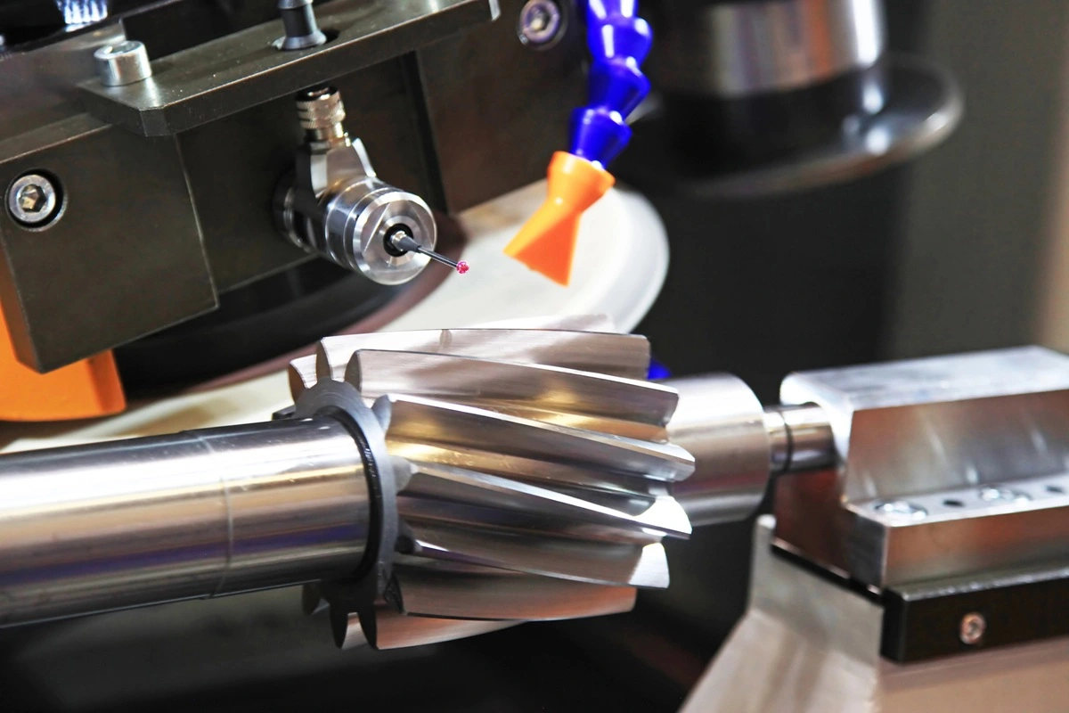
High Precision and Tight Tolerances
Advanced CNC machining can achieve tolerances as tight as 0.005 mm. Unlike the often rougher finishes of casting, automated cutters produce precise tooth profiles. This minimizes vibration and noise. Such accuracy is critical for aerospace and robotics applications operating at high speeds.
Design Flexibility with Five Axis Machining
Machines using five axes approach the workpiece from multiple angles in a single setup. Engineers can produce complex geometries, like spiral bevels, that standard tools often cannot cut. Designs can be modified and machined rapidly, bypassing expensive mold costs.
Ideal for Prototyping and Production in Low Volumes
Injection molding typically requires expensive tooling and weeks of lead time. CNC machining avoids these initial costs. It allows engineers to quickly order custom CNC machining parts directly from CAD data, creating functional prototypes or small batches that accelerate product testing and market entry.
Handling Difficult Materials
CNC tooling cuts materials that are difficult to mold.
- Titanium: Machined while minimizing heat buildup to preserve its ratio of strength to weight.
- PEEK: Cut cleanly to maintain chemical resistance and reduce thermal distortion.
- Hardened Steel: Processed after heat treatment to support durability under heavy loads.
FAQ
Do I Need a 3D CAD Model to Order Custom Gears?
Yes. 3D files (STEP or IGES) enable rapid quoting and programming. 2D drawings (PDF) also work for simple designs. For broken physical parts, shops offer reverse engineering to create the required files.
What Is the Difference Between Gears, Pinions, and Sprockets?
Engagement defines the difference. Gears mesh directly with other gears. Sprockets drive chains or tracks without contacting another wheel. A pinion is the smaller gear in a meshing pair.
When Should I Choose CNC Machining Over Traditional Hobbing?
Choose CNC for prototypes, complex shapes, or tight deadlines. Hobbing requires specific tooling, adding cost and setup time. CNC uses standard cutters to start rapidly. It suits volumes under 1,000 parts or delivery in days, not weeks.
Conclusion
The right gear configuration defines the lifespan of your equipment. Engineering success requires pairing the correct design with the optimal material. While stock parts offer convenience, they rarely survive demanding environments. For complex geometries or custom prototypes, partnering with a precision manufacturer like Rollyu ensures the dimensional accuracy and material integrity necessary for lasting reliability.